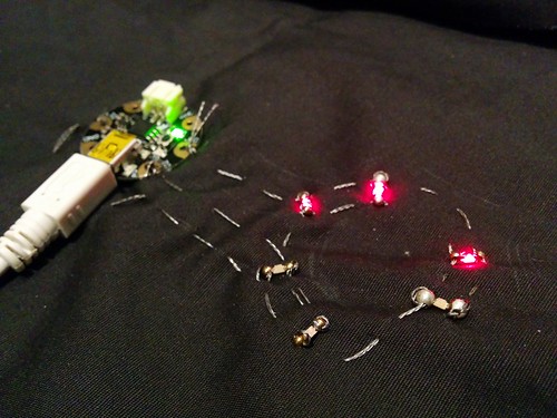
Want to drive more LEDs with fewer IO pins? Then you might be interested in the Charlieplexing technique. I’ve written an example sketch can drive six LEDs each with 8-bit PWM using the three IO pins on the Adafruit GEMA microcontroller and is a fairly easy sewable LED sequin project since there are no crossed wires when it is stitched with conductive thread. Enjoy the short video of it in action below and read on for more details…
Solder:Time Desk Clock
The Spikenzie Labs Solder:Time Desk Clock is a fun through-hole kit to solder together. It includes a snap-together lasercut acrylic case with a really nice red tinted screen that increases the contrast on the 20×7 red LED matrix. Plus it is totally hackable with quite a few unused pins available for expansion (like Holly’s sunrise alarm clock).
The kit is available from Adafruit and I’ve written more information on information on programming custom firmware for the Arduino-compatible ATmega328P that is the brains of the clock.
AVRFID, now with 35-bit support
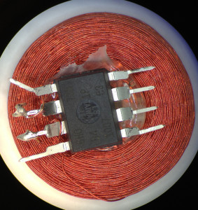
Last year we wrote about building HID Proxcard RFID tags with attiny85 microcontrollers (based on Micah’s avrfid.s code). The C version only supported classic 26-bit cards, but I recently needed to support the “secure” HID Corporate 1000 35-bit format.
Based on Daniel Smith’s writeup on the format and some digging around, I figured out that the MFG_CODE for this format is 10-bits long with the value 0x005. He also pointed out that the 26-bit firmware had the wrong code — it is not the 20-bit code 0x01002, but is instead the 19-bit code 0x0801 and the bottom bit is part of the parity computation for the card id. If you’re using a HID branded Proxcard reader, the value that it outputs is the entire data portion, including all of the parity bits, but does not include the MFC_CODE part. If anyone knows of a table of these codes, please let me know!
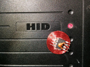
I’ve updated my firmware with these changes and it works great. Emulating a 35-bit card takes 846 bytes of flash (nine more than the 26-bit cards since the state machine stores one bit per byte), so it might be possible to port this to the attiny10. I’ve also found that the tags work much better with a small capacitor across the two clock pins, as shown in the above photo.
AVR RFID Multipass
I was inspired by Beth’s avrfid.S project to try to build a replacement for the multiple HID Prox cards that I carry for work. Her design is simultaneously a technical tour-de-force and an example of how badly we can abuse the Atmel chips. Here is the entire schematic:

There is no connection to power and ground: the chip is powered through leakage current from the input pins. The AC waveform is fed directly into the pins: the internal protection diodes rectify it. During negative parts of the wave the silicon die’s inherent capacitance maintains state. The CPU clock is driven by the AC as well and depends on the ability of the coil to drive more current than the chip when DDRB is configured to pull the pins to the same potential. It’s truly amazing that this works at all.
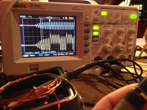
The firmware she wrote in macro assembler is easy to understand and straightfoward, but filled the entire 8 KB flash on the ATTiny85 when compiled for HID Prox cards. Unlike the CW modulated EM41xx cards that just load the coil for thirty RF cycles to send a baseband one and don’t load the coil to send a baseband zero, the HID cards use Frequency Shift Keying (FSK) modulation. In FSK a baseband zero is sent by cycling the load on the coil for 50 cycles at a frequency of 4 RF cycles, and a baseband one is sent by cycling the load every 5 RF cycles. Beth’s code loads the coil by setting the two bits in DDRB to 1 while holding PORTB at 0, which places a short across the coil by putting both ends at the same potential.
While it turns out that my dream of automatically selecting the right RFID card doesn’t work, read on for details of how to build your own HID compatible RFID devices and some overview of the hand-tuned assembly necessary to fit the RFID timing. Continue reading »


