Working with the HDSP 2111
Uncategorized
Add comments
May 302010
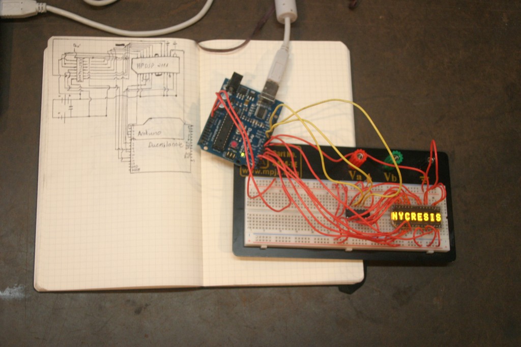
During Hackday I worked on a display for the Stabby ID.
I have six or so HDSP 2111 units lying around. They also come in green and red led models.
Read on for Schematic and Demo Arduino Source
Requirements:
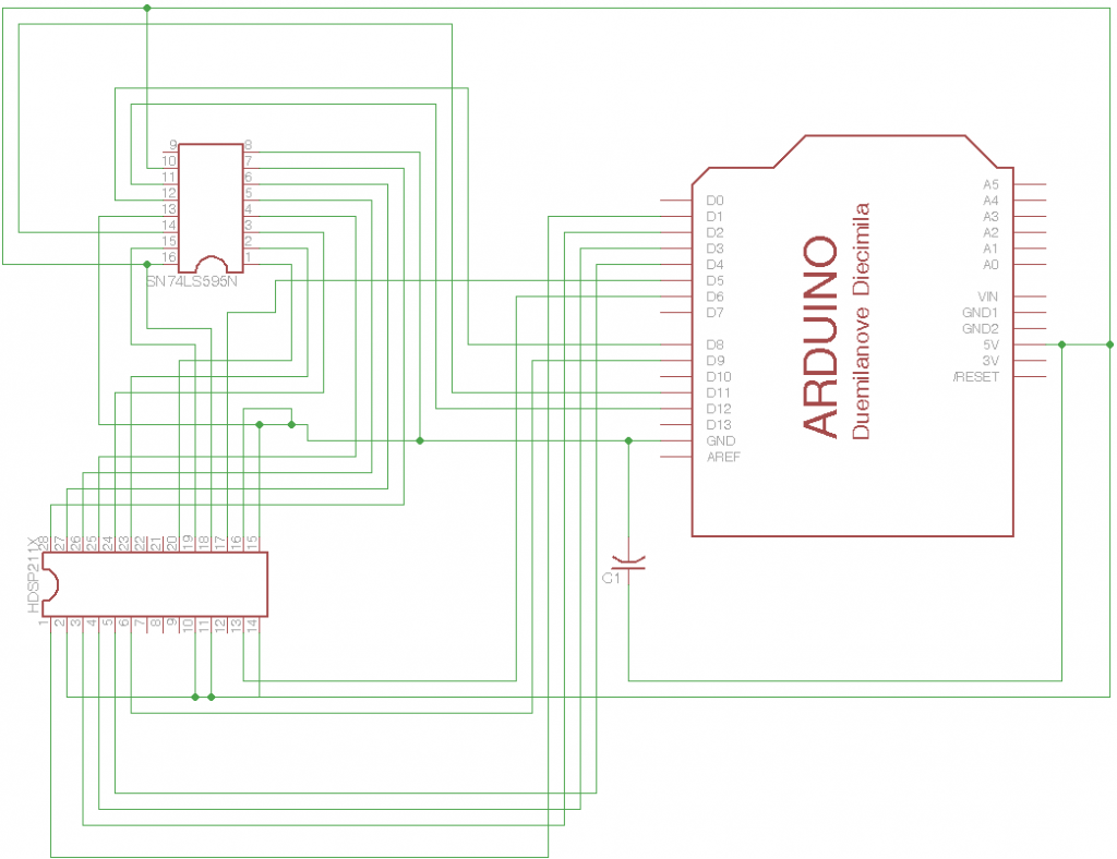
1 HDSP 211x LED Display
1 SN74LS595N Low Current Shift Register
1 Arduino compatible board
1 current reference capacitor ( just for safety )
Schematic:
Source:
8 Responses to “Working with the HDSP 2111”
Comments (6) Pingbacks (2)


dox_dropped();
Just a quick note: I have one of these displays. Powering it with 5V made it go hot and unstable with the schematics above. Connecting the 3.3V out instead of 5V made it work fine.
You have an HTTP/HTTPS dissonance between this page’s protocol and the Pastebin embed script you’re using that’s causing the code not to show up. Update the to and it’ll work again.
Sorry, those tags probably got mangled. Maybe this will work:
You have an HTTP/HTTPS dissonance between this page’s protocol and the Pastebin embed script you’re using that’s causing the code not to show up. Update the
toand it’ll work again.There’s a pcb on https://github.com/koendv/retroleds
I’m just wondering why you used the shift reg. It is a parrel beast so throw 8 bits at a time to it.